CAROUSEL ELECTRIC GENERATOR
US Patent 5,625,241 29th April 1997 Inventor: Harold E. Ewing et al. This is a modified excerpt of the patent which shows a compact, self-powered, combined permanent magnet motor and electrical generator. There is some additional information at the end of the patent.
_____________________________________________
A permanent magnet generator or motor having stationary coils positioned in a circle, or a rotor on which are
mounted permanent magnets grouped in sectors and positioned to move adjacent to the coils, and a carousel
carrying corresponding groups of permanent magnets through the centres of the coils, the carousel moves with
the rotor by virtue of its being magnetically coupled to it.
___________________________________________________
INVENTORS
Ewing, Harold E. (Chandler, AZ, US)
Chapman, Russell R. (Mesa, AZ, US)
Porter, David R. (Mesa, AZ, US)
INVENTORS
Ewing, Harold E. (Chandler, AZ, US)
Chapman, Russell R. (Mesa, AZ, US)
Porter, David R. (Mesa, AZ, US)
_________________________
ASSIGNEE:
Energy Research Corporation (Mesa, AZ)
US Patent References:
3610974 Oct, 1971 Kenyon 310/49.
4547713 Oct, 1985 Langley et al. 318/254.
5117142 May, 1992 Von Zweygbergk 310/156.
5289072 Feb, 1994 Lange 310/266.
5293093 Mar, 1994 Warner 310/254.
5304883 Apr, 1994 Denk 310/180.
Energy Research Corporation (Mesa, AZ)
US Patent References:
3610974 Oct, 1971 Kenyon 310/49.
4547713 Oct, 1985 Langley et al. 318/254.
5117142 May, 1992 Von Zweygbergk 310/156.
5289072 Feb, 1994 Lange 310/266.
5293093 Mar, 1994 Warner 310/254.
5304883 Apr, 1994 Denk 310/180.
BACKGROUND OF THE INVENTION
There are numerous applications for small electric generators in ratings of a few kilowatts or less. Examples include electric power sources for emergency lighting in commercial and residential buildings, power sources for remote locations such as mountain cabins, and portable power sources for motor homes, pleasure boats, etc. In all of these applications, system reliability is a primary concern. Because the power system is likely to sit idle for long periods of time without the benefit of periodic maintenance, and because the owner-operator is often inexperienced in the maintenance and operation of such equipment, the desired level of reliability can only be achieved through system simplicity and the elimination of such components as batteries or other secondary power sources which are commonly employed for generator field excitation.
Another important feature for such generating equipment is miniaturization particularly in the case of portable equipment. It is important to be able to produce the required level of power in a relatively small generator. Both of these requirements are addressed in the present invention through a novel adaptation of the permanent magnet generator or magneto in a design that lends itself to high frequency operation as a means for maximizing power output per unit volume.
DESCRIPTION OF THE PRIOR ART
Permanent magnet generators or magnetos have been employed widely for many years. Early applications of such generators include the supply of electric current for spark plugs in automobiles and airplanes. Early
telephones used magnetos to obtain electrical energy for ringing. The Model T Ford automobile also used
magnetos to power its electric lights. The present invention differs from prior art magnetos in terms of its novel physical structure in which a multiplicity of permanent magnets and electrical windings are arranged in a fashion which permits high-speed/high-frequency operation as a means for meeting the miniaturization requirement. In addition, the design is enhanced through the use of a rotating carousel which carries a multiplicity of field source magnets through the centres of the stationary electric windings in which the generated voltage is thereby induced.
SUMMARY OF THE INVENTION
In accordance with the invention claimed, an improved permanent magnet electric generator is provided with a capability for delivering a relatively high level of output power from a small and compact structure. The
incorporation of a rotating carousel for the transport of the primary field magnets through the electrical windings in which induction occurs enhances field strength in the locations critical to generation. It is, therefore, one object of this invention to provide an improved permanent magnet generator or magneto for the generation of electrical power. Another object of this invention is to provide in such a generator a relatively high level of electrical power from a small and compact structure. A further object of this invention is to achieve such a high level of electrical power by virtue of the high rotational speed and high frequency operation of which the generator of the invention is capable.
A further object of this invention is to provide such a high frequency capability through the use of a novel field structure in which the primary permanent magnets are carried through the centres of the induction windings of the generator by a rotating carousel.
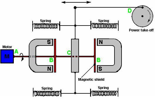
A still further object of this invention is to provide a means for driving the rotating carousel without the aid of mechanical coupling but rather by virtue of magnetic coupling between other mechanically driven magnets and those mounted on the carousel.
A still further object of this invention is to provide an enhanced capability for high speed/high frequency operation through the use of an air bearing as a support for the rotating carousel.
Yet another object of this invention is to provide in such an improved generator a sufficiently high magnetic field density in the locations critical to voltage generation without resort to the use of laminations or other media to channel the magnetic field.
Further objects an advantages of the invention will become apparent as the following description proceeds and the features of novelty which characterize the invention will be pointed out with particularity in the claims annexed to and forming a part of this specification.
BRIEF DESCRIPTION OF THE DRAWINGS
The present invention may be more readily described by reference to the accompanying drawings, in which:

Fig.1 is a simplified perspective view of the carousel electric generator of the invention;

Fig.2 is a cross-sectional view of Fig.1 taken along line 2--2;


Fig.4 is a cross-sectional view of Fig.3 taken along line 4--4;

degree sector of the generator of the invention as viewed in the direction of arrow 5 of Fig.3;

generator of the invention as viewed in the direction of arrow 6 in Fig.1;

relative to the permanent magnets;

voltage configuration of the generator;

configuration;

Fig.10 is a schematic diagram showing a series/parallel connection of generator windings for intermediate current and voltage operation;

embodiment of the invention;

Fig.12A and Fig.12B show upper and lower views of the carousel magnets of Fig.11;


positioned at each station; and

DESCRIPTION OF THE PREFERRED EMBODIMENT


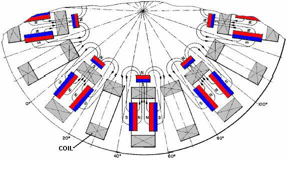
stator and in one twenty degree sector of the rotor. In the first implementation of the invention, there are eighteen identical stator sectors, each incorporating a winding or coil 17 wound about a rectangular coil frame or bobbin. Coil 17 is held by a stator frame 18 which may also serve as an outer wall of frame 11.
The rotor is also divided into eighteen sectors, nine of which incorporate three permanent magnets each,
including an inboard rotor magnet 19, an upper rotor magnet 21 and a lower rotor magnet 22. All three of these magnets have their south poles facing coil 17, and all three are mounted directly on rotor frame 23 which is secured directly to drive shaft 14. The other nine sectors of the rotor are empty, i.e. they are not populated with magnets. The unpopulated sectors are alternated with the populated sectors so that adjacent populated sectors are separated by an unpopulated sector as shown in Fig.3 and Fig.6. With reference again to Fig.2, generator 10 also incorporates a carousel 24. The carousel comprises nine pairs of carousel magnets 25 clamped between upper and lower retainer rings 26 and 27, respectively. The lower retainer ring 27 rests inside an air bearing channel 28 which is secured to stator 18 inside the bobbin of coil 17. Air passages (not shown) admit air into the space between the lower surface of ring 27 and the upper or inside surface of channel 28. This arrangement comprises an air bearing which permits carousel 24 to rotate freely within the coils 17 about rotational axis 29 of rotor frame 23. Carousel 24 is also divided into 18 twenty-degree sectors, including nine populated sectors interspersed with nine unpopulated sectors in an alternating sequence. Each of the nine populated sectors incorporates a pair of carousel magnets as described in the preceding paragraph.

The geometrical relationship between the rotor magnets, the carousel magnets and the coils, is further clarified by Fig.3, Fig.4 and Fig.5. In each of the three figures, the centre of each populated rotor sector is shown aligned with the centre of a coil 17. Each populated carousel sector, which is magnetically locked into position with a populated rotor sector, is thus also aligned with a coil 17.


Coil supports and other stationary members located within magnetic field patterns are fabricated from Delrin or Teflon plastic or equivalent materials. The use of aluminum or other metals introduce eddy current losses and in some cases excessive friction.
As shown in Fig.5, carousel magnets 25A and 25B stand on edge, parallel with each other, their north poles facing each other, and spaced one inch apart. When viewed from directly above the carousel magnets, the space between the two magnets 25A and 25B appears as a one-inch by two-inch rectangle. When the carousel magnet pair 25 is perfectly locked into position magnetically, upper rotor magnet 21 is directly above this one-inch by two-inch rectangle, lower rotor magnet 22 is directly below it, and their one-inch by two-inch faces are directly aligned with it, the south poles of the two magnets 21 and 22 facing each other.
In like manner, when viewed from the axis of rotation of generator 10, the space between carousel magnets 25A and 25B again appears as a one-inch by two-inch rectangle, and this rectangle is aligned with the one-inch by two-inch face of magnet 19, the south pole of magnet 19 facing the carousel magnet pair 25. Rotor magnets 19, 21 and 22 are positioned as near as possible to carousel magnets 25A and 25B while still
allowing passage for coil 17 over and around the carousel magnets and through the space between the carousel magnets and the rotor magnets.
In an electric generator, the voltage induced in the generator windings is proportional to the product of the number of turns in the winding and the rate of change of flux linkages that is produced as the winding is rotated through the magnetic field. An examination of magnetic field patterns is therefore essential to an understanding of generator operation.
In generator 10, magnetic flux emanating from the north poles of carousel magnets 25A and 25B pass through the rotor magnets and then return to the south poles of the carousel magnets. The total flux field is thus driven by the combined MMF (magneto motive force) of the carousel and field magnets while the flux patterns are determined by the orientation of the rotor and carousel magnets.


flux into the desired path. This arrangement replaces the function of magnetic yokes or laminations of more
conventional generators. The flux linkages produced by magnets 25A and 25B are opposite in sense regardless of the rotational position of coil 17 including the case where coil 17 is aligned with the carousel and rotor magnets as well as for the same coils when they are aligned with an unpopulated rotor sector.
Taking into account the flux patterns of Fig.4 and Fig.6 and recognizing the opposing sense conditions just
described, net flux linkages for a given coil 17 are deduced as shown in Fig.7.

In Fig.7, net flux linkages (coil-turns x lines) are plotted as a function of coil position in degrees. Coil position is here defined as the position of the centreline 35 of coil 17 relative to the angular scale shown in degrees in Fig.6. (Note that the coil is stationary and the scale is fixed to the rotor. As the rotor turns in a clockwise direction, the relative position of coil 17 progresses from zero to ten to twenty degrees etc.).
At a relative coil position of ten degrees, the coil is centred between magnets 25A and 25B. Assumingsymmetrical flux patterns for the two magnets, the flux linkages from one magnet exactly cancel the flux linkages from the other so that net flux linkages are zero. As the relative coil position moves to the right, linkages from magnet 25A decrease and those from magnet 25B increase so that net flux linkages build up from zero and passes through a maximum negative value at some point between ten and twenty degrees. After reaching the negative maximum, flux linkages decrease, passing through zero at 30 degrees (where coil 17 is at the centre of an unpopulated rotor sector) and then rising to a positive maximum at some point just beyond 60 degrees. This cyclic variation repeats as the coil is subjected successively to fields from populated and unpopulated rotor sectors.
As the rotor is driven rotationally, net flux linkages for all eighteen coils are altered at a rate that is determined by the flux pattern just described in combination with the rotational velocity of the rotor. Instantaneous voltage induced in coil 17 is a function of the slope of the curve shown in Fig.7 and rotor velocity, and voltage polarity changes as the slope of the curve alternates between positive and negative.
It is important to note here that a coil positioned at ten degrees is exposed to a negative slope while the adjacent coil is exposed to a positive slope. The polarities of the voltages induced in the two adjacent coils are therefore opposite. For series or parallel connections of odd and even-numbered coils, this polarity discrepancy can be corrected by installing the odd and even numbered coils oppositely (odds rotated end for end relative to evens) or by reversing start and finish connections of odd relative to even numbered coils. Either of these measures will render all coil voltages additive as needed for series or parallel connections. Unless the field patterns for populated and unpopulated sectors are very nearly symmetrical, however, the voltages induced in odd and even numbered coils will have different waveforms. This difference will not be corrected by the coil reversals or reverse connections discussed in the previous paragraph. Unless the voltage waveforms are very nearly the same, circulating currents will flow between even and odd-numbered coils. These circulating currents will reduce generator efficiency

To prevent such circulating currents and the attendant loss in operating efficiency for non symmetrical field
patterns and unmatched voltage waveforms, the series-parallel connections of Fig.8 may be employed in a high current, low-voltage configuration of the generator. If the eighteen coils are numbered in sequence from one toeighteen according to position about the stator, all even-numbered coils are connected in parallel, all odd numbered coils are connected in parallel, and the two parallel coil groups are connected in series as shown with reversed polarity for one group so that voltages will be in phase relative to output cable 16.


For intermediate current and voltage configurations, various series-parallel connections may be employed. Fig.10, for example, shows three groups of six coils each connected in series. Circulating currents will be avoided so long as even-numbered coils are not connected in parallel with odd-numbered coils. Parallel connection of series-connected odd/even pairs as shown is permissible because the waveforms of the series pairs should be very neatly matched.

In another embodiment of the invention, the two large (two-inch by two-inch) carousel magnets are replaced by three smaller magnets as shown in Fig.11, Fig.12 and Fig.13. The three carousel magnets comprise an inboard carousel magnet 39, an upper carousel magnet 41 and a lower carousel magnet 42 arranged in a U-shaped configuration that matches the U-shaped configuration of the rotor magnets 19, 21 and 22. As in the case of the first embodiment, the rotor and carousel magnets are present only in alternate sectors of the generator.

shown in Fig.12, each magnet measures one inch by two inches by one half inch thick. The south pole occupies
the bevelled one-inch by two-inch face and the north pole is at the opposite face.


The modification of the carousel structure as described in the foregoing paragraphs can be taken one step further with the addition of a fourth carousel magnet 52 at each station as shown in Fig.14. The four carousel magnets 39, 41, 42 and 52 now form a square frame with each of the magnet faces (north poles) facing a corresponding inside face of the coil 17. Carousel magnets for this modification may again be as shown in Fig.12. An additional rotor magnet 53 may also be added as shown, in alignment with carousel magnet 52. These additional modifications further enhance the field pattern and the degree of coupling between the rotor and the carousel. The carousel electric generator of the invention is particularly well suited to high speed, high frequency operation where the high speed compensates for lower flux densities than might be achieved with a magnetic medium for routing the field through the generator coils. For many applications, such as emergency lighting, the high frequency is also advantageous. Fluorescent lighting, for example, is more efficient in terms of lumens per watt and the ballasts are smaller at high frequencies.
While the present invention has been directed toward the provision of a compact generator for specialisedgenerator applications, it is also possible to operate the device as a motor by applying an appropriate alternating voltage source to cable 16 and coupling drive shaft 14 to a load.

The power control circuit incorporates a solid state switch in the form of a power transistor or a MOSFET. It responds to the control signal 58 by turning the solid state switch ON and OFF to initiate and terminate coil excitation. Instantaneous voltage amplitude supplied to the coils during excitation is controlled by means of potentiometer P. Motor speed and torque are thus responsive to potentiometer adjustments.
The device is also adaptable for operation as a motor using a commutator and brushes for control of coil
excitation. In this case, the commutator and brushes replace the programmable logic controller and the power
control circuit as the means for providing pulsed DC excitation. This approach is less flexible but perhaps more
efficient than the programmable control system described earlier. It will now be recognised that a novel and useful generator has been provided in accordance with the stated objects of the invention, and while but a few embodiments of the invention have been illustrated and described it will be apparent to those skilled in the art that various changes and modifications may be made without departing from the spirit of the invention or from the scope of the appended claims.
Additional Info
The “carousel” is formed from two circular plastic channels like this:

These channels are placed, one below and one above, nine pairs of carousel magnets. Each carousel magnet sits in the lower channel:

And these magnets are secured as a unit by an identical plastic channel inverted and placed on top of the magnet
set:

spins inside the coils because the nine pairs of magnets in the ring, lock in place opposite the matching nine pairs of magnets in the rotor and the magnetic force and rotor rotation causes the ring to spin inside the coils.