This is a simple electrical generator powered by permanent magnets alone. This generator can
also be used as a motor. The construction is not particularly complicated as shown below:
It is arranged so that permanent magnets are associated with every second coil set around the rotor.
Operation is self-powered and the magnet arrangement is clearly defined:
And the physical arrangement of the device is not particularly complicated:
The generator is patented under US patent. The patent has a detailed description of the Generator. It is patent 5,625,241. This is a patent which is definitely worth reading and considering, especially since it is not a complicated presentation on the part of the authors, Harold Ewing, Russell Chapman and David Porter. This seemingly very effective generator appears to be overlooked at the present time. It seems quite clear that permanent magnet motors are a wholly viable option for the home constructor and they are capable of substantial power outputs over long periods, however, it should be noted that motors using magnets alone are notoriously difficult to get operational and while it can be done, motors which use moving shielding or pulsed electrical shielding are much more viable for the first-time constructor. Google for the patent if you need it now, or check back at my blog, for the patent during my subsequent posts..
This is a magnet/electric motor generator which produces an output greater than the input necessary to run it created by John Ecklin. This creation earned him a US patent. There are two styles of operation. The main illustration for the first is:
Here, the (clever) idea is to use a small low-power motor to rotate a magnetic shield to mask the pull of two magnets. This causes a fluctuating magnet field which is used to rotate a generator drive. In the diagram above, the motor at point ‘A’ rotates the shaft and shielding strips at point ‘B”. These rectangular mu-metal strips form a very conductive path for the magnetic lines of force when they are lined up with the ends of the magnets and they effectively shut off the magnet pull in the area of point ‘C’. At point ‘C’, the spring-loaded
traveller is pulled to the left when the right-hand magnet is shielded and the left hand magnet is not shielded.
When the motor shaft rotates further, the traveller is pulled to the right when the left-hand magnet is shielded and the right hand magnet is not shielded. This oscillation is passed by mechanical linkage to point ‘D’ where it is used to rotate a shaft used to power a generator. As the effort needed to rotate the magnetic shield is relatively low, it is claimed that the output exceeds the input and so can be used to power the motor which rotates the magnetic shield.
The second method for exploiting the idea is shown as:
Here, the same shielding idea is utilized to produce a reciprocating movement which is then converted to two rotary motions to drive two generators. The pair of magnets ‘A’ are placed in a housing and pressed towards each other by two springs. When the springs are fully extended, they are just clear of the magnetic shield ‘B’. When a small electric motor (not shown in the diagram) moves the magnetic shield out of the way, the two magnets are strongly repelled from each other as their North poles are close together. This compresses the springs and through the linkages at ‘C’ they turn two shafts to generate output power.
A modification of this idea is the Ecklin-Brown Generator. In this arrangement, the movable magnetic shielding arrangement provides a direct electrical output rather than a mechanical movement:
Here, the same motor and rotating magnetic shield arrangement is used, but the magnetic lines of force are
blocked from flowing through a central I-piece. This I-piece is made of laminated iron slivers and has a pickup coil or coils wound around it. The device operates as follows:
In the position shown on the left, the magnetic lines of force flow downwards through the pickup coils. When the motor shaft has rotated a further ninety degrees, the situation on the right occurs and there, the magnetic lines of force flow upwards through the pickup coils. This is shown by the blue arrows in the diagram. This reversal of magnetic flux takes place four times for every rotation of the motor shaft. While the Ecklin-Brown design assumes that an electric motor is used to rotate the mu-metal shield, there does not seem to be any reason why the rotation should not be done with a permanent magnet motor.
Another effective power take-off system is that used by the “Phi Transformer” (“Phi” is pronounced “Fi”). In this design, the magnetic drag is reduced by containing the magnetic flux in a laminated iron ring or “toroid”. Again, the design expects an electric motor to be used to spin the rotor, but there does not seem to be any great reason why a permanent magnet motor should not be used instead. Toroidal shapes are clearly important in many devices which pull in additional energy from the environment, even to the extent that Bob Boyce warns against the high-frequency sequential pulsing of coils wound on a toroid yoke, producing a rotating magnetic field as unpredictable surge events can generate some 10,000 amps of additional current which will burn out the circuit components and can very well trigger a radiant energy build up which can create a lightning strike. Bob
himself has been hit by just such a lightning strike and he is lucky to have survived. Lesser systems such as the toroid transformer used in Bob’s electrolyser system are safe even though they generate a power gain. So the many toroidal system designs are definitely worth examining.
Today, we will be looking at THE WANG SHUM HO 5KW GENERATOR an over unity electricity generator.
we are going straight into the design.
Major Components
1. Cup containing a vibration fluid 2. A legged device to act as an unbalanced wheel 3. An unbalanced wheel with vibration damper fluid and one permanent magnet 4. an inner rotating shaft with a disc containing permanent magnets. 5. Outer cylinder with fixed permanent magnets 6. magnetic shielding material 7. On and off control via disruption of magnetic field using shielding material
1. Cup with vibration fluid
wang did the following experiment over 30 years ago: - An inverted 4 legged stool was put on top of a bowl of water - 4 persons all putting the right hand on the tip of the legs -the water, the cup, then the stool will rotate clockwise and the 4 persons would walk/run - use left hand, roation will be anti-clockwise.
4 persons would walk/run Earn money with an alertpay account
- use left hand, rotation will be anti-clockwise.
This experiment can be repeated, but there is no obvious logical explanation. this concept was used in the wang device. the vibration fluid contains 3-8 metallic powder suspended in a liquid. when this cup of fluid is placed in the magnetic field, the metallic powder will move, generating circular motion. there will be interaction with the magnetic field and extraction of energy.
Welcome to my Blog of Free Energy Devices. This blog takes you through the design of some notable free energy devices.
Disclaimer
I state here categorically, that this information is only for informative reasons, and that I am not liable for any shotcomings that may arise as a result of the use of this information. I donot gaurantee that what I present here will work for you or anyone. So any loses that you may incure as a result of using this blog, are solely on your shoulders alone.
Without Wasting time trying to convince anybody about the possible existence of free energy devices, I simply state here that You are Free to Believe, Accept and Do what ever you think or want to believe. For any right thinking man in this century will understand that it is absolutely necessary to have an open mind. Newton's Laws which have stood the test of time, have sudenly been reduced to theories, because they don't hold in certain frames of reference. Others have held for centuries, that the Earth was flat, I don't need to inform you that it is spherical. what about the recent advances in technology. wireless networks, cellphones, computers etc, were these possible about a hundred years ago?
I do not suggest that this set of information covers every possible device, nor that my description is by any means the complete and definitive statement of everything to be known on the subject
Free energy devices are termed so, because they use resources that we have not yet fully understood. The Ether has not yet been fully understood, but with time, we will come to understand it better for The fact of the matter is, that we are sitting in a vast field of energy which we can’t see.. that is why many people tend to say that the concept of free energy devices contradicts the law of conservation of energy. But the concept does not. “Free-Energy Devices” or “Zero-Point Energy Devices” are the names applied to systems which appear to produce a higher output power than their input power.
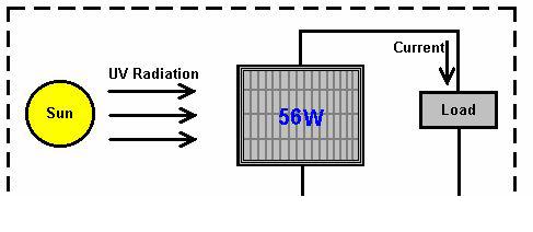
Take an electrical solar panel, viewed in isolation, this looks like (and actually is) a Free-Energy device if it is set up out of doors in daylight, as current is supplied to the load (radio, battery, fan, pump, or whatever) without the user providing any input power. Again, Power Out with no Power In. Try it in darkness and you find a different result because the whole picture is reversed:
The energy which powers the solar panel comes from the sun.. Only some 17% of the energy reaching the solar panel is converted to electrical current. This is most definitely not a contravention of the Law of Conservation of Energy. This needs to be explained in greater detail. The Law of Conservation of Energy applies to closed systems, and only to closed systems. If there is energy coming in from the environment, then the Law of Conservation of Energy just does not apply, unless you take into account the energy entering the system from outside.
It is probably worth while, at this point, to explain the basics of Zero-Point Energy. The experts in Quantum Mechanics refer to how the universe operates as “Quantum Foam”. Every cubic centimetre of “empty” space is foaming with energy, so much in fact, that if it were converted using Einstein’s famous equation E = mC2 (that is Energy = Mass x a very big number), then it would produce as much matter as can be seen by the most powerful telescope. There is actually nothing “empty” about space. So why can’t we see anything there? Well, you can’t actually see energy. All right then, why can’t you measure the energy there? Well, two reasons actually, firstly, we have never managed to design an instrument which can measure this energy, and secondly, the energy is changing direction incredibly rapidly, billions and billions and billions of times each second.
There is so much energy there, that particles of matter just pop into existence and then pop back out again. Half of these particles have a positive charge and half of them have a negative charge, and as they are evenly spread out in three-dimensional space, the overall average voltage is zero. So, if the voltage is zero, what use is that as a source of energy? The answer to that is “none” if you leave it in it’s natural state. However, it is possible to change the random nature of this energy and convert it into a source of unlimited, everlasting power which can be used for all of the things we use mains electricity for today - powering motors, lights, heaters, fans, pumps, etc, the power is there for the taking.
So, how do you alter the natural state of the energy in our environment? Actually, quite easily. All that is needed is a positive charge and a negative charge, reasonably near each other. A battery will do the trick, as will a generator, as will an aerial and earth, as will an electrostatic device like a Wimshurst machine. When you
generate a Plus and a Minus, the quantum foam is affected. Now, instead of entirely random plus and minus
charged particles appearing everywhere, the Plus which you created gets surrounded by a sphere of minus charge particles popping into existence all around it. Also, the Minus which you created, gets surrounded by a spherical-shaped cloud of plus-charge particles popping into existence all around it. The technical term for this situation is “broken symmetry” which is just a fancy way of saying that the charge distribution of the quantum foam is no longer evenly distributed or “symmetrical”. In passing, the fancy technical name for your Plus and Minus near each other, is a “dipole” which is just a techno-babble way of saying “two poles: a plus and a minus” when you make a battery, the chemical action inside the battery creates a Plus terminal and a Minus terminal. Those poles actually distort the universe around your battery, and causes vast streams of energy to radiate out in every direction from each pole of the battery. Why doesn’t the battery run down? Because the energy is flowing from the environment and not from the battery. If you were taught basic physics or electrical theory, you will probably have been told that the battery used to power any circuit, supplies a stream of electrons which flows around the circuit. Sorry Chief - it just ain’t like that at all. What really happens is that the battery forms a “dipole” which nudges the local environment into an unbalanced state which pours out energy in every direction, and some of that energy from the environment flows around the circuit attached to the battery. The energy does not come from the battery. Well then, why does the battery run down, if no energy is being drawn from it to power the circuit? Ah, that is the really silly thing that we do. We create a closed-loop circuit (because that’s what we have always done) where the current flows around the circuit, reaches the other battery terminal and immediately destroys the battery’s “dipole”. Everything stops dead in it’s tracks. The environment becomes symmetrical again, the massive amount of readily available free-energy just disappears and you are back to where you started from. But, do not despair, our trusty battery immediately creates the Plus and Minus terminals again and the process starts all over again. This happens so rapidly that we don’t see the breaks in the operation of the circuit and it is the continual recreation of the dipole which causes the battery to run down and lose it’s power. Let me say it again, the battery does not supply the current that powers the circuit, it never has and it never will - the current flows into the circuit from the surrounding environment. What we really need, is a method of pulling off the power flowing in from the environment, without continually destroying the dipole which pushes the environment into supplying the power. That is the tricky bit, but it has been done. If you can do that, then you tap into an unlimited stream of inexhaustible energy, with no need to provide any input energy to keep the flow of energy going. In passing, if you want to check out the details of all of this, Lee and Yang were awarded the Nobel Prize for Physics in 1957 for this theory which was proved by experiment in that same year.
Check back My Blog for subsequent posts on some Free energy devices, which you can construct if you so desire.
Remember. Any devices you undertake to construct, you do so at your own risk. I am not liable for any loses or injuries sustained from the use of this information.
 It is arranged so that permanent magnets are associated with every second coil set around the rotor.
 And the physical arrangement of the device is not particularly complicated: